Today, Zusie was featured on the front page of SweClockers, one of Sweden's biggest computer enthusiast sites.
In the 48 hours since it was published, it has been almost 5000 times, voted 4.8 out of 5.0 (tied for the first place with another great build), and received over a hundred overwhelmingly positive comments from members. Cool! :-)
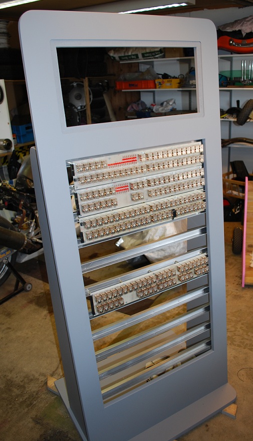
Zusie the Relay Computer - Zusie mounted in cabinet
This video displays Zusie the Relay Computer with all boards as well as the control panel mounted in its wodden cabinet. It also shows the machine from many angles while it's running an iterative program.
May 23, 2011
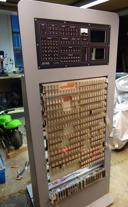
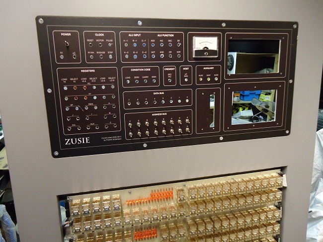
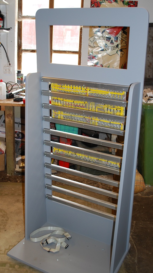
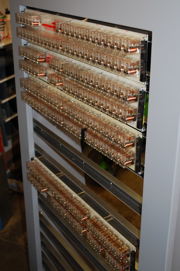
All boards have been mounted on the cabinet, and I am now working on the front panel and the wiring on the rear site.
May 1, 2011
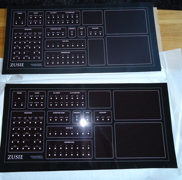
I have started mounting all the boards on the cabinet. I am also waiting for my front panel design to come back from the printer's.
March 11, 2011
A small side-project of Zusie has evolved: A really cool flip-disc display that will show the contents of part of Zusie's memory space.
It is now almost finished, and will be mounted on Zusie's soon-to-be control panel. Here are some videos showing the progress of this device.
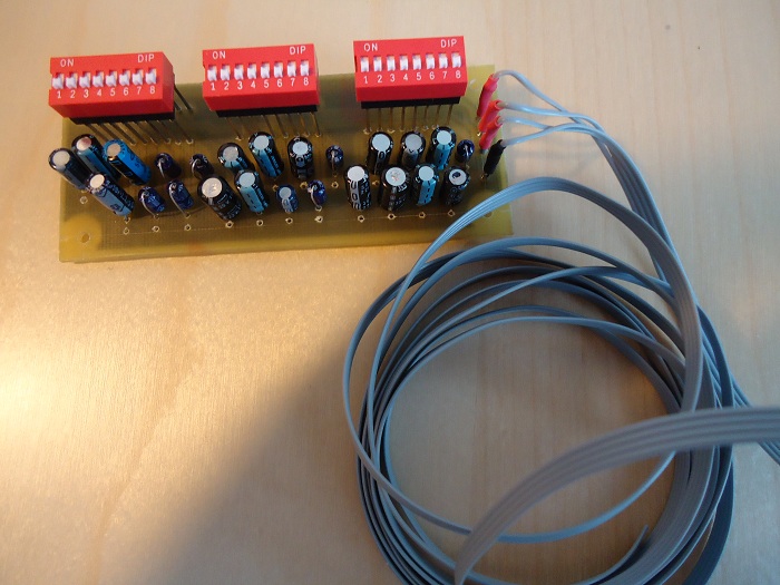
FlipDisc Display - First Experiment
As a peripheral project to Zusie, this is a display that will be used to show the contents of part of its memory area. It's a display constructed from flipdiscs (the same technique used on buses etc), that is, tiny discs that can flip to show either a black or a yellow side. They are flipped by reversing the current through a tiny coil under each disc. Once in a state, the disc will stay there until flipped again, even if power is cut, by way of magnetic remanence. This video shows a first test of my flipdisc display. It uses a PIC processor, which right now just flips the discs repeatedly, but later it will read the address and data buses of Zusie and display the memory contents on the display. The DIP switch on the control board will be used to set the base address of the display in Zusie's memory space.
Zusie FlipDisc Display - Almost Finished!
This video shows Zusie's flipdisc display, which will be used to visualize a region of Zusie's memory. It will sit on Zusie's address and data buses, and show with tiny black and yellow metallic discs the values present at a range of locations in Zusie's RAM memory. The discs are hinged above a coil, and by reversing the current through the coil, we can make the discs flip.
The display itself consists of 14 columns of 8 bits each. Each column corresponds to a byte of memory. The column in addressed by the lower 4 bits of the address bus.
The whole process is controlled by a PIC microcontroller, which continously reads the data bus and outputs any changed bits to the driving circuitry which drives current through the appropriate coil.
Right now we emulate the buses with the small switches at the bottom. The four on the right is the address of the column, and the eight on the left are the data bits.
There is also a cool test mode, which is entered by removing a jumper block, which will make the whole column continuously go on and off.
February 15, 2011
Zusie the Relay Computer - Stack test at Extreme Speed
This video shows the same program as the Stack Test video, but after some trimming of the oscillator and timing circuits, I really max out the speed of the machine. This results in very fast execution (for a relay machine...) and glorious sound!!
February 12, 2011
I'm working on the wooden cabinet, some microcode timing related circuits, and a special treat that I will soon show off!
January 2, 2011
Zusie the Relay Computer - Stack test
A test execution of the stack functionalities of Zusie (PUSH and POP of values).
The movie is annotated to help you understand what's happening.
Zusie has a 12-bit stack pointer that grows downwards from 0xFFF.
November 20, 2010
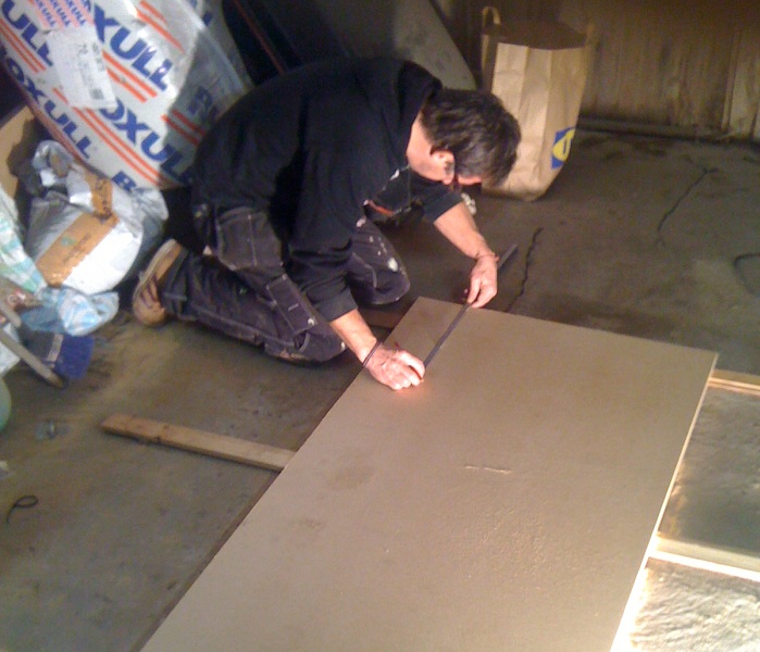
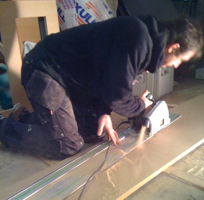
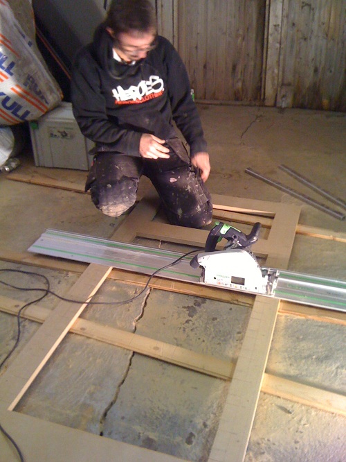
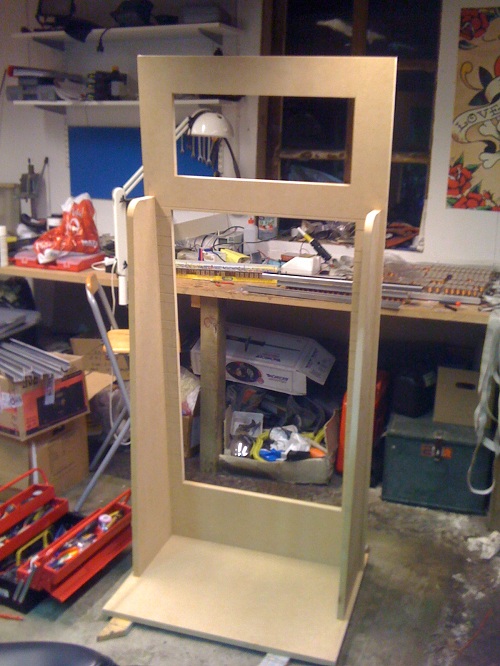
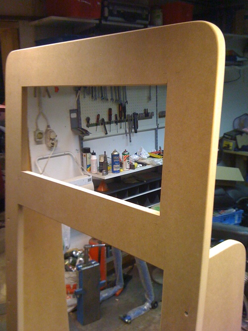
I am doing the woodwork on the cabinet for Zusie together with a friend. Pictures soon.
Zusie has progressed beyond the point of microprograms - it's now possible to write simple programs in assembly language, run them through a homebrew assember and upload them to Zusie's program memory as machine code.
In the video, Zusie executes the following program:
LDLA b10101010 ; Loads this literal binary value into A
:again
NOTAC ; Negates A and puts into C
MOVCA ; Puts negated value back into A
SBR again ; Do an unconditional (short) branch back to again
Notice the alternating bit patters in the A and C registers! This means the assembly execution works, including branch logic.
I run the machine at low speed to avoid potential problems....
Much work on Zusie right now focuses around writing and debugging microcode for all assembly instructions. It will be a pretty straightforward CISC-style reasonably orthogonal instruction set.
September 7, 2010
First Microprogram
Zusie runs her first microprogram! A short program is entered into the micro-control store and runs repeatedly (the last instruction is a reset instruction that resets the microsequencer). This is the first video showing the interaction between the logic/memory board and the relay boards. It also show the new microsequencer relay board (the board with green LEDs) in action. This board is used to generate incrementing addresses for the microprogram memory.
September 6, 2010
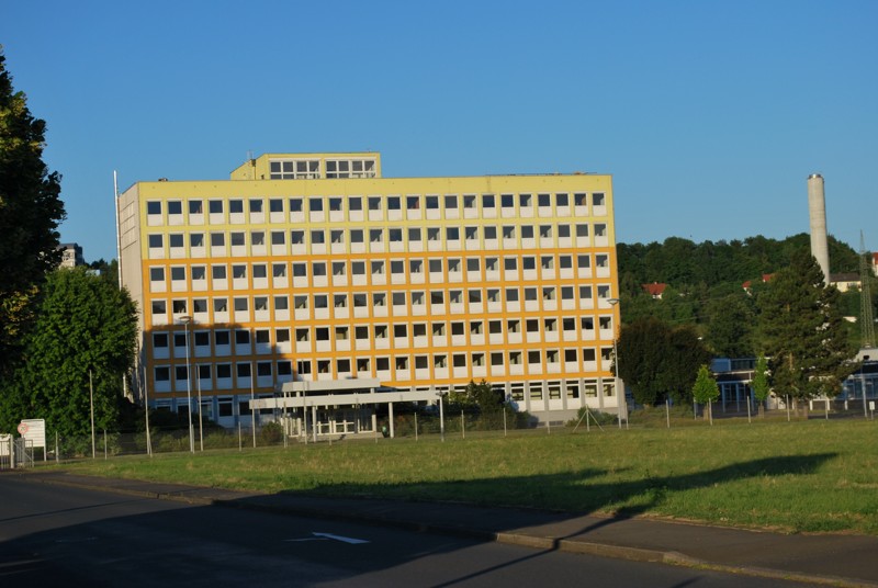
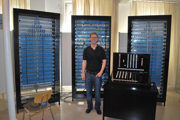
Slightly off-topic, here are some extremely geeky pictures from my trip to Germany this summer, which naturally included many Zuse sights.
July 29, 2010
Third Experiment
This video shows the microcode sequencer at work. The microcode are the internal sub-instructions that make up the machine language instructions of the computer. It is the innermost conductor of all operations happening in the machine. This board holds the sequencer for the microcode, i.e. the register holding the microcode address and the incrementer. The board takes as input a single pulse from the system clock (currently provided by the small oscillator board at the top), and uses this to increment and store the next microcode address. The complexity of the board is due to the fact that the microcode sequencing should be able to run in parallel with the operation of the rest of the computer.
July 15, 2010
I am lousy when it comes to keeping this page updated - I apologize. But don't despair, Zusie is far from dead - or finished! :-)
A lot of work as been done, and a lot more remains.
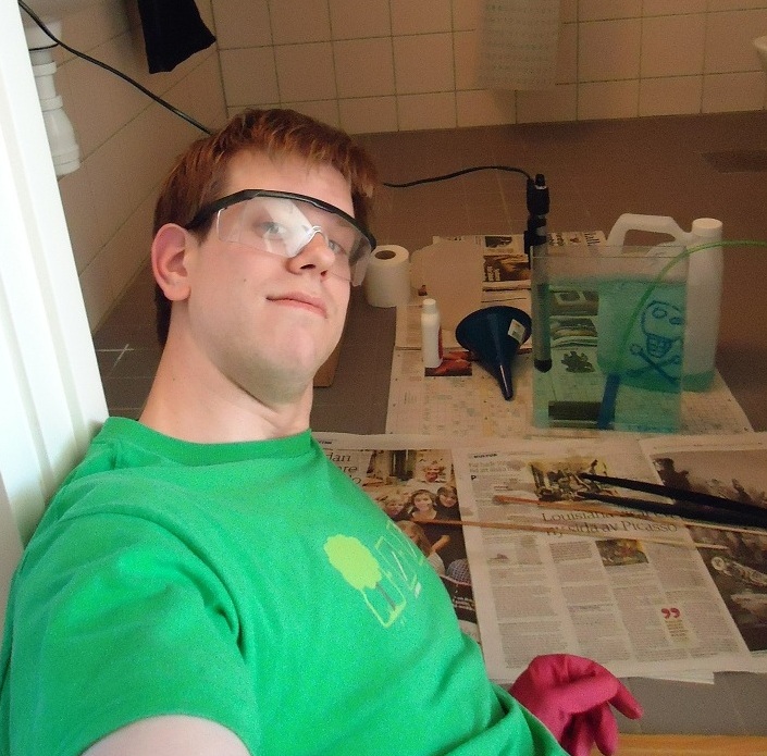
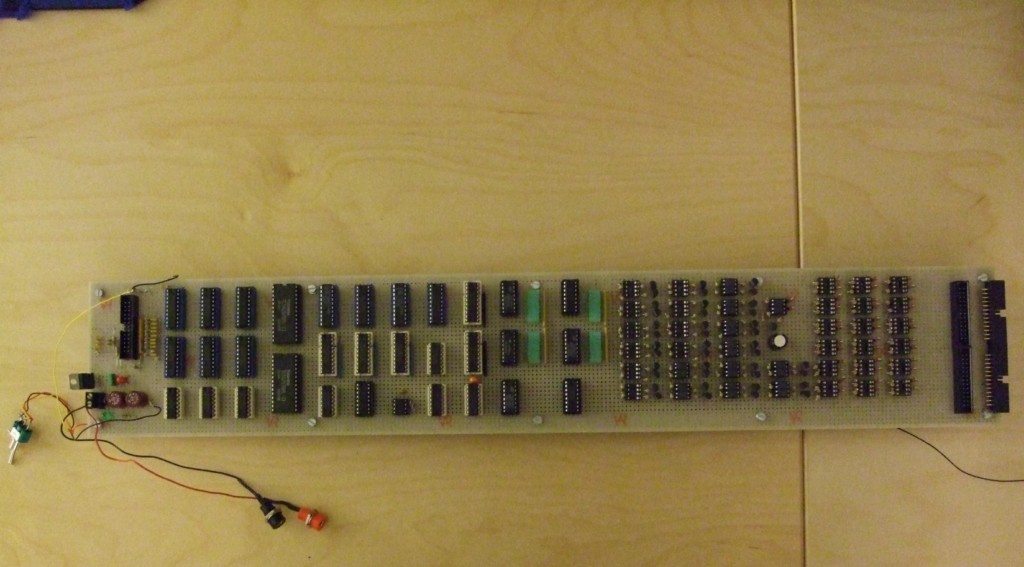
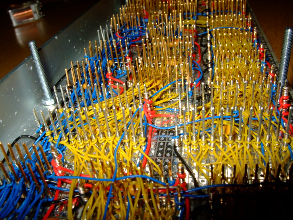
Among other things, I have finished the RAM/microcode board, which is implemented using normal ICs. This is the only board that will not use relays
to perform its function.
It is wire-wrapped, a skill which I had great fun learning. The pictures below show this card.
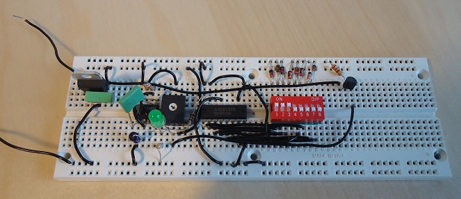
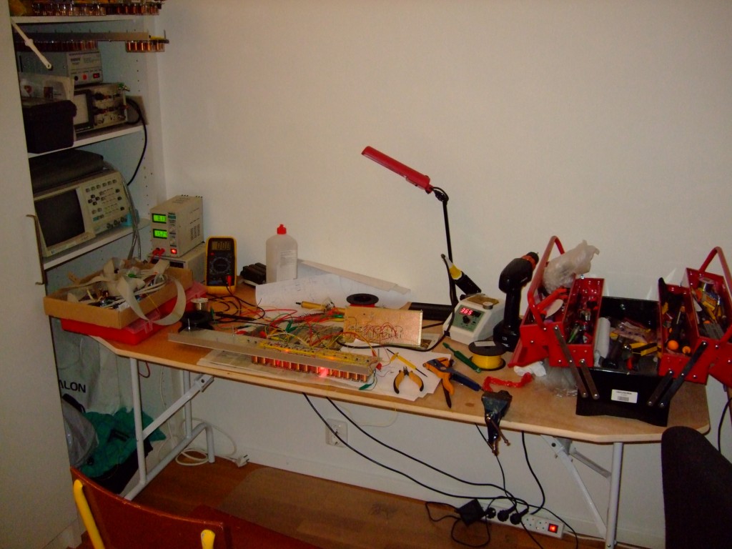
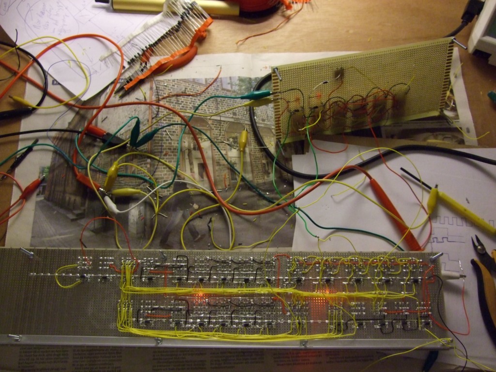
Right now I am working on the microsequecing. The pictures below show the unfinished microinstruction sequencer hooked up to a
debug circuit. You'll also see my current workplace in my new apartment. :)
Stay tuned for more soon!
September 17, 2009
Since my last video upload, I have finished two more cards: A 2x12 bit register card that will hold the program counter and stack pointer registers, and a 16-bit incrementer/decrementer with latching. This functionality will be used for e.g. pushing/popping the stack and for program counting.
Below are three videos that shows tests of this functionality.
Zusie, the Relay Computer - Second Experiment
This video shows a decrement operation. The soon-to-be stack pointer register is decremented from 0xFFF downwards. It is also a bit of a speed test - I run it at an insanely high speed for a relay computer :)
Zusie the Relay Computer - Second Experiment, bonus movie
This video shows Zusie the relay computer doing some incrementation. See the other "second experiment" movie for more info. This video also features some footage of my cozy workshop! :)
Light Pollution by Zusie the Relay Computer
This video just shows the cool lighting effects that the two "second experiment" cards produce when the lights in the room are turned out. High-intensity LEDs are cool!
August 16, 2009
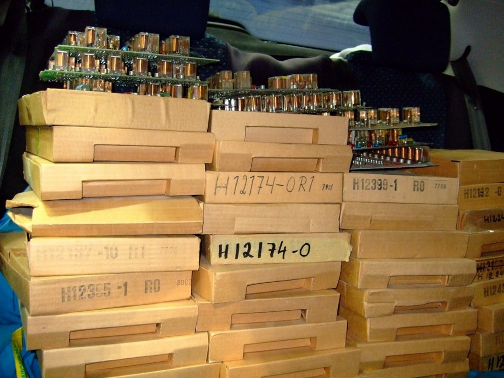
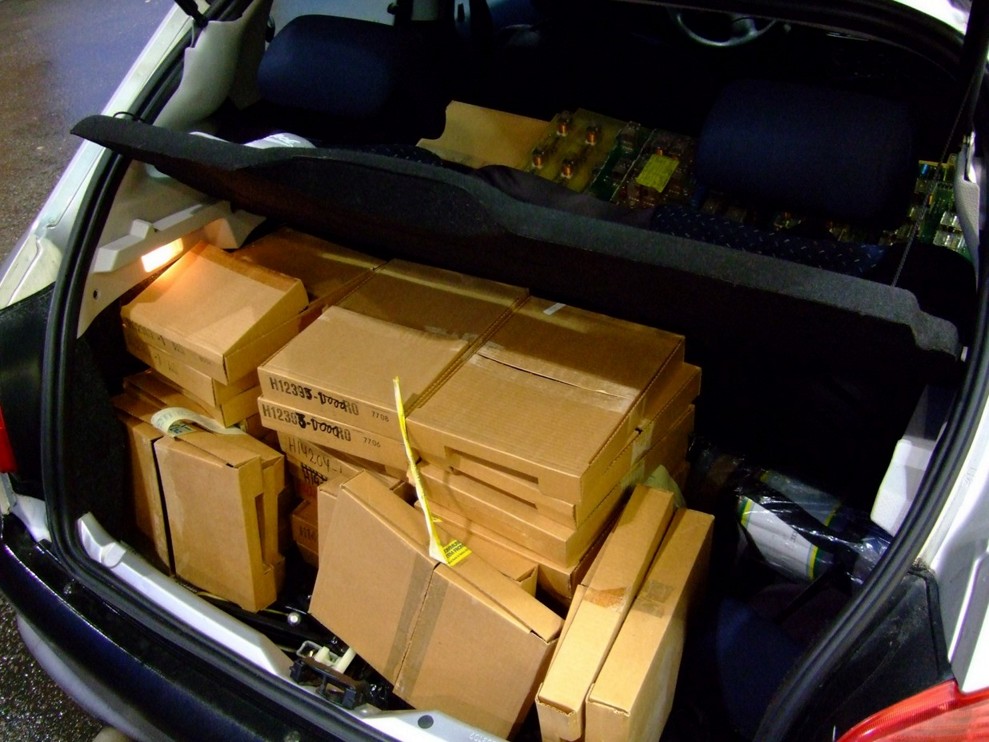
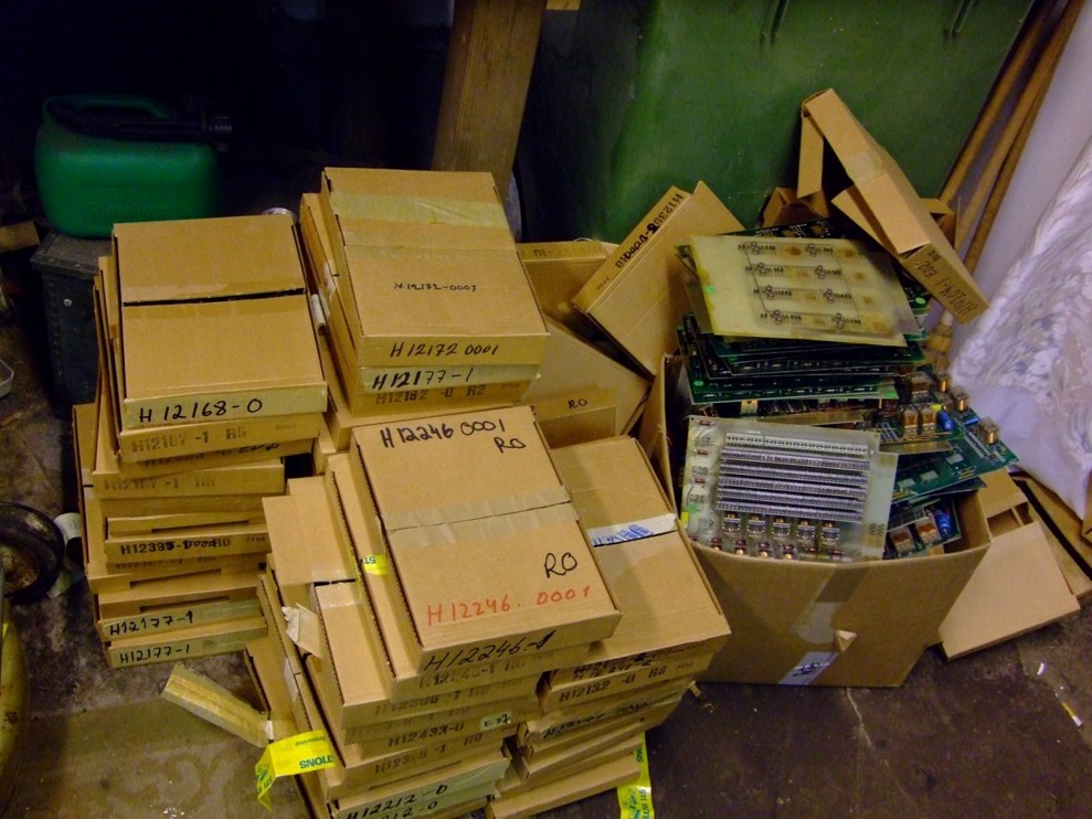
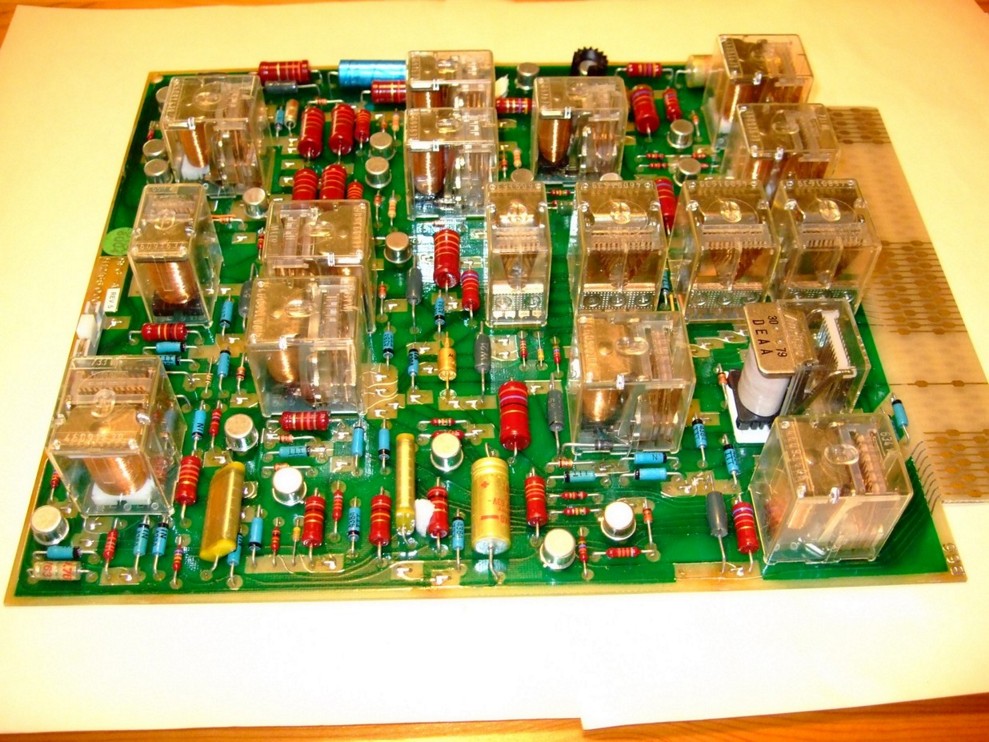
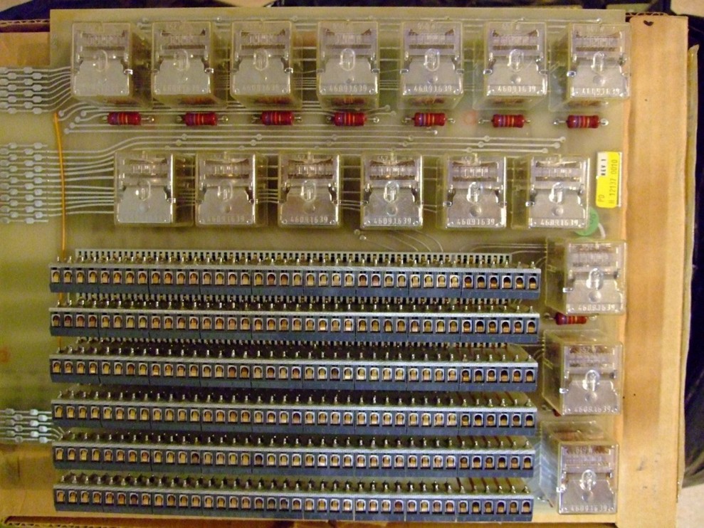
Here are some image galleries for your enjoyment. First we have some pictures from my 850 kilometer trip to buy 100 discarded circuit boards and then desoldering them for relays:
Some misc images from construction:
July 27, 2009
First Experiment
This video shows the first three cards in operation. The top card is the adder/incrementer, the second is logical and ALU control, and the bottom one holds 4 x 8-bit registers (3 accumulator + 1 instruction reg). Red lights are data bits, blue are control lines. The control lines are driven by a PC through the smaller relays on the small card at the very top.
This first experimental cicuit iteratively increments the value in the "A" register (the row of LEDs at the top-left of lower card). The operation is as follows:
1) Select increment operation of ALU (shown by blue LED on the top card) and select A register as input. A+1 appears on data bus. 2). Store data bus in B register (bottom row of LEDs on bottom card). 3). Load B register onto data bus. 4). Store data bus in A register. 5). Repeat from 1.
Watch the binary value of the bottom LED rows increase by one and enjoy the beautiful sound of the relays clicking!
Check back here soon again to see the progress and enjoy more glorious relay clicking!